Symmetrical components
In electrical engineering, the method of symmetrical components is used to simplify analysis of unbalanced three phase power systems under both normal and abnormal conditions.
Contents |
Description
In 1918 Charles Legeyt Fortescue presented a paper[1] which demonstrated that any set of N unbalanced phasors (that is, any such polyphase signal) could be expressed as the sum of N symmetrical sets of balanced phasors, for values of N that are prime. Only a single frequency component is represented by the phasors.
In a three-phase system, one set of phasors has the same phase sequence as the system under study (positive sequence; say ABC), the second set has the reverse phase sequence (negative sequence; CBA), and in the third set the phasors A, B and C are in phase with each other (zero sequence). Essentially, this method converts three unbalanced phases into three independent sources, which makes asymmetric fault analysis more tractable.
By expanding a one-line diagram to show the positive sequence, negative sequence and zero sequence impedances of generators, transformers and other devices including overhead lines and cables, analysis of such unbalanced conditions as a single line to ground short-circuit fault is greatly simplified. The technique can also be extended to higher order phase systems.
Physically, in a three phase winding a positive sequence set of currents produces a normal rotating field, a negative sequence set produces a field with the opposite rotation, and the zero sequence set produces a field that oscillates but does not rotate between phase windings. Since these effects can be detected physically with sequence filters, the mathematical tool became the basis for the design of protective relays, which used negative-sequence voltages and currents as a reliable indicator of fault conditions. Such relays may be used to trip circuit breakers or take other steps to protect electrical systems.
The analytical technique was adopted and advanced by engineers at General Electric and Westinghouse and after World War II it was an accepted method for asymmetric fault analysis.
The three-phase case
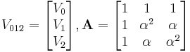
Symmetrical components are most commonly used for analysis of three-phase electrical power systems. If the phase quantities are expressed in phasor notation using complex numbers, a vector can be formed for the three phase quantities. For example, a vector for three phase voltages could be written as
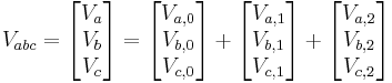
where the subscripts 0, 1, and 2 refer respectively to the zero, positive, and negative sequence components. The sequence components differ only by their phase angles, which are symmetrical and so are  radians or 120°. Define the operator
  phasor vector forward by that angle.

Note that α3 = 1 so that α−1 = α2.
The zero sequence components are in phase; denote them as:
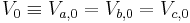
and the other phase sequences as:
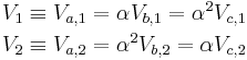
Thus,
where
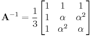
Conversely, the sequence components are generated from the analysis equations
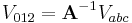
where
An intuitive feeling
The phasors  form a closed triangle (e.g., outer voltages or line to line voltages). To find the synchronous and inverse components of the phases, take any side of the outer triangle and draw the two possible equilateral triangles sharing the selected side as base. These two equilateral triangles represent a synchronous and inverse system. If the phasors V were a perfectly synchronous system the vertex of the outer triangle not on the base line would be at the same position as the corresponding vertex of the equilateral triangle representing the synchronous system. Any amount of inverse component would mean a deviation from this position. The deviation is exactly 3 times the inverse phase component. The synchronous component is in the same manner 3 times the deviation from the "inverse equilateral triangle". The directions of these components are correct for the relevant phase. It seems counter intuitive that this works for all three phases regardless of the side chosen but that is the beauty of this illustration.
See also
References
- ^ Charles L. Fortescue, "Method of Symmetrical Co-Ordinates Applied to the Solution of Polyphase Networks". Presented at the 34th annual convention of the AIEE (American Institute of Electrical Engineers) in Atlantic City, N.J. on 28 July 1918. Published in: AIEE Transactions, vol. 37, part II, pages 1027-1140 (1918). For a brief history of the early years of symmetrical component theory, see: J. Lewis Blackburn, Symmetrical Components for Power Engineering (Boca Raton, Florida: CRC Press, 1993), pages 3-4.
- J. Lewis Blackburn Symmetrical Components for Power Systems Engineering, Marcel Dekker, New York (1993). ISBN 0-8247-8767-6
- William D. Stevenson, Jr. Elements of Power System Analysis Third Edition, McGraw-Hill, New York (1975). ISBN 0-07-061285-4.
- History article from IEEE on early development of symmetrical components, retrieved May 12, 2005.
- Westinghouse Corporation, Applied Protective Relaying, 1976, Westinghouse Corporation, no ISBN, Library of Congress card no. 76-8060 - a standard reference on electromechanical protective relays